Moment of Inertia Lab
Title: Moment of Inertia Lab
Date: 3/3/15
Partner: Steph Kinsella
Date: 3/3/15
Partner: Steph Kinsella
Purpose
The purpose of this lab was to determine an object's moment of inertia using both geometric formulas and quantities of angular motion.
Theory
Moment of inertia is a property of any rolling or spinning object that measures the object's resistance to change in a rotational direction.
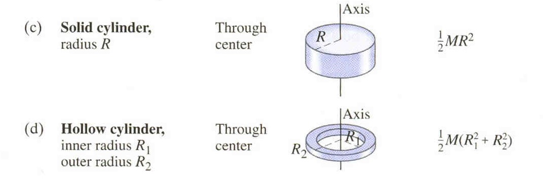
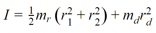
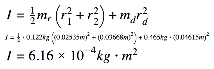
In order to calculate the moment of inertia geometrically, the shapes of the objects must be identified. Because the object consists of two uniform shapes (a hollow cylinder or ring and a solid cylinder or disk) the following equations for uniform objects can be used. The moment of inertia is intended to be calculated for the total object, so the equations are added together to get:
In order to calculate the moment of inertia geometrically, the shapes of the objects must be identified. Because the object consists of two uniform shapes (a hollow cylinder or ring and a solid cylinder or disk) the following equations for uniform objects can be used. The moment of inertia is intended to be calculated for the total object, so the equations are added together to get:
|
|
|
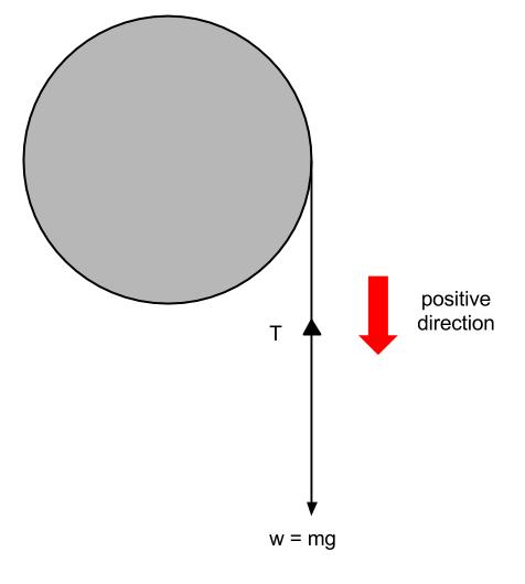
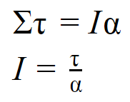
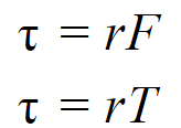
Using quantities of angular motion, an additional equation must be derived. Using the relationship between torque and moment of inertia as well as the free body diagram for the apparatus, and noting that the force causing the torque is the tension, the following is true:
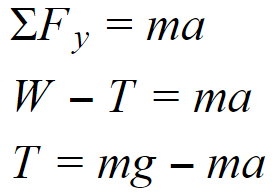
Then, summing the forces and substituting the quantity of tension back into the above equation, we get:
|
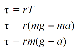
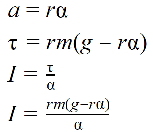
Finally, substituting the relationship between angular and tangential acceleration into the original relationship gives us a final equation.
Experimental Technique
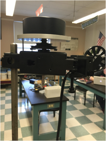
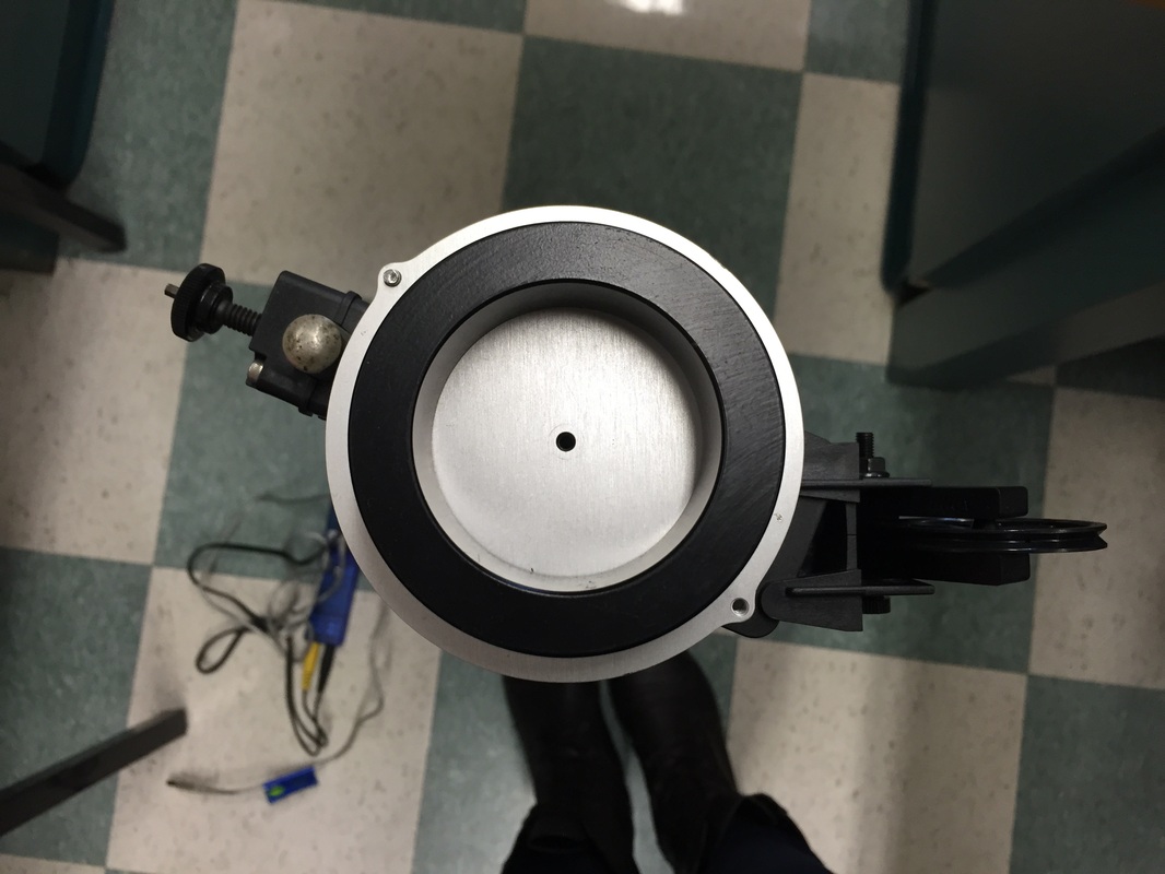
After derivations, measurements of the masses and radii of the disk and ring need to be taken as well as the radii of the base of the rotational motion sensor. The apparatus, set up as shown below, should have the disk sitting firmly upon the motion sensor and the ring secured atop the disk. A string is wrapped tightly around the base of the system and led to the pulley at a parallel angle to reduce unnecessary friction.
A mass hanger is attached to the end of the string and allowed to drop, causing the system at the top to rotate. The masses are varied with each trial of the experiment to gain a variety of different data points.
Using Data Studio, rotational velocity is measured and rotational acceleration is found by finding the slope of the velocity versus time graph.
|
|
Data
The mass of the ring was measured to be 0.122 kg.
The mass of the disk was measured to be 0.465 kg.
The inner diameter of the ring was measured to be 5.070 cm, making the inner radius 0.02535 m.
The outer diameter of the ring was measured to be 7.335 cm, making the outer radius 0.03668 m.
The diameter of the disk was measured to be 9.230 cm, making the radius of the disk 0.04615 m.
The diameter of the part of the rotational motion sensor around which the system rotated was measured to be 4.520 cm, making its radius 0.0226 m.
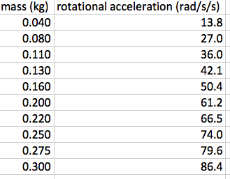
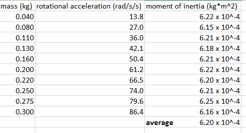
The following angular acceleration data was collected using varying masses and a rotational motion sensor in Data Studio.
The mass of the disk was measured to be 0.465 kg.
The inner diameter of the ring was measured to be 5.070 cm, making the inner radius 0.02535 m.
The outer diameter of the ring was measured to be 7.335 cm, making the outer radius 0.03668 m.
The diameter of the disk was measured to be 9.230 cm, making the radius of the disk 0.04615 m.
The diameter of the part of the rotational motion sensor around which the system rotated was measured to be 4.520 cm, making its radius 0.0226 m.
The following angular acceleration data was collected using varying masses and a rotational motion sensor in Data Studio.
Analysis
Using the measurements made above and the equation for the geometric moment of inertia of the object, the value was determined to be 6.16 x 10^-4 kg*m^2, as shown below.
A mass versus angular acceleration graph was created for the data.
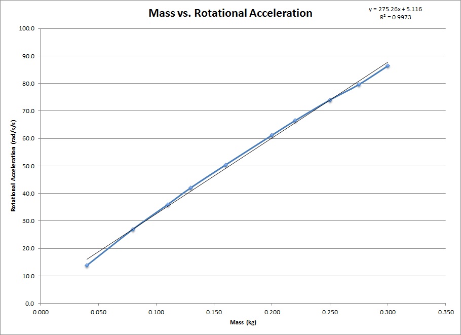
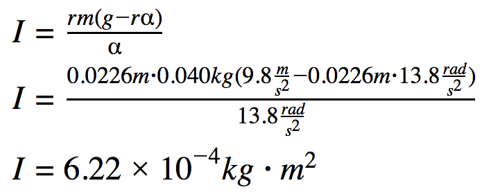
Using the measured accelerations, moments of inertia were determined for each data point and an average was calculated. The average moment of inertia was determined to be 6.20 x 10^-4 kg*m^2. A sample calculation is also shown below.
|
|
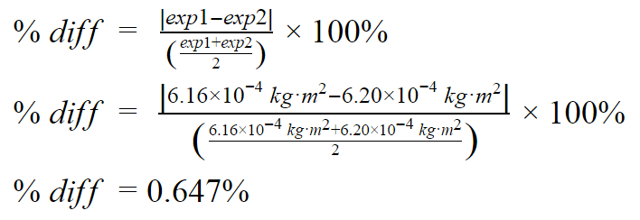
Finally, percent difference between the geometric and measured values was calculated to be 0.647%.
Conclusion
The purpose of this lab was to find the moment of inertia of the ring and disk system using two methods. Geometrically, the moment of inertia was found to be 6.16 x 10^-4 kg*m^2. Using experimental quantities, the moment of inertia was calculated to be 6.20 x 10^-4 kg*m^2. The percent difference between the two values was 0.647%.
Although small, the error could be attributed to our classification of the pulley. We treated the pulley as a massless, frictionless system when in fact, this is not the case. The pulley does produce a small amount of friction with the string. It also has its own mass and therefore its own moment of inertia, which should be included in the geometric calculation but for our purposes, was not.
Although small, the error could be attributed to our classification of the pulley. We treated the pulley as a massless, frictionless system when in fact, this is not the case. The pulley does produce a small amount of friction with the string. It also has its own mass and therefore its own moment of inertia, which should be included in the geometric calculation but for our purposes, was not.
References
Giancoli, D. (2009). Physics for Scientists and Engineers (4th ed.). Upper Saddle River, N.J.: Pearson Prentice Hall.
Lahs Physics (n.d.). Retrieved October 6, 2014, from www.lahsphysics.weebly.com
Moment of Inertia. (n.d.). Retrieved March 8, 2015, from http://www.engineeringtoolbox.com/moment-inertia-torque-d_913.html
Lahs Physics (n.d.). Retrieved October 6, 2014, from www.lahsphysics.weebly.com
Moment of Inertia. (n.d.). Retrieved March 8, 2015, from http://www.engineeringtoolbox.com/moment-inertia-torque-d_913.html
