Circular Motion Lab
Title: Circular Motion Lab
Date: 11/25/14
Partner: Abbey Applegate
Date: 11/25/14
Partner: Abbey Applegate
Purpose
The purpose of this lab is to investigate the effect of mass on centripetal force using both measured and calculated values.
Theory
|
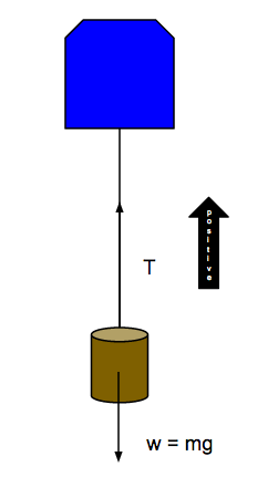
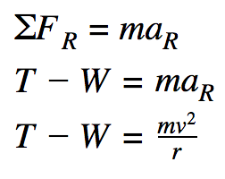
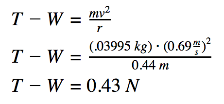
In the diagram at right, the apparatus rotates around the center of the blue force sensor, allowing the upwards direction to be noted as the radial, or positive, direction. Then, we can sum the forces in the radial direction as follows:
The left side of the equation indicates what a tared force sensor measures, while the right side gives the formula to calculate the centripetal force from mass, velocity, and radius.
|
|
Experimental Technique
|
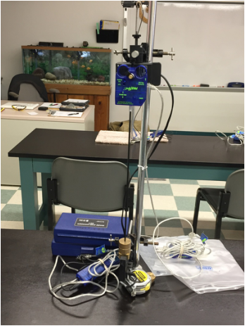
The apparatus was set up as shown on the left. In order to vary the mass, radius and velocity must be held relatively constant. A constant radius is obtained aligning the proper measurement with the center of mass, which, because the fixture used for security weighs approximately as much as each mass, is roughly the geometric center of the masses. In order for the force sensor to measure T-W as it needs to in the equation, we must tare the force sensor by zeroing it after we attach the mass.
Before recording data, make sure to change the flag length in Data Studio to the width of the masses in the area where it will cross the laser in the photo gate. After collecting data for each data run, select a velocity on the graph from the most linear portion and use the smart tool to find the corresponding centripetal force on the other graph. Try to select similar velocities from trial to trial to keep the velocity constant for calculations. Record the velocity and centripetal force for five trials. |
Data
|
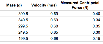
The constant radius was 0.44 m.
The flag length, or the diameter of the mass, was .0360 m. The gallery below shows the graphs from which the measurements were obtained. The measured data is shown in the data table at right. |
|
Analysis
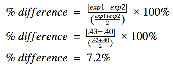
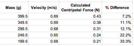
Then, using the derived equation, calculated values were obtained using the same masses and velocities as above , as shown below. Percent error was also calculated in the method displayed at center. The results are shown in the table.
|
|
|
Conclusion
The purpose of this lab was to assess the effect of mass on centripetal force. Centripetal force can be affected by mass, velocity, and radius, meaning that it is crucial to hold the other two variables as constant as possible when changing one of them. Thus, it is very easy to cause error to occur between the calculated and measured values.
Possible sources of error include inconsistent velocities, skew in the radius measurement, or improper placement based on the center of mass, especially if the base of the pendulum twisted at all through the photo gate to alter the way it perceived the flag length. The most error was most likely obtained through the velocity measurement, as this was the hardest to keep consistent. The measurement system did not always provide a data point as close to the mark as would be desirable, and thus we were forced to choose one slightly above or below the original mark.
In order to improve this measurement, I suggest taking a larger data set for each mass so that there are more precise values to choose from. A mark should be made so that the pendulum can be swung more consistently to the desired height and reach the designated velocity. Finally, the center of the photo gate should read the circular masses rather than the square base so as to minimize flag length errors.
References
Giancoli, D. (1998). Physics: Principles with Applications (5th ed.). Upper Saddle River, N.J.: Prentice Hall.
Lahs Physics (n.d.). Retrieved October 6, 2014, from www.lahsphysics.weebly.com
Lahs Physics (n.d.). Retrieved October 6, 2014, from www.lahsphysics.weebly.com
